Quick Answer
Solar fire safety setbacks vary: US (NEC 690.12) requires 3-foot paths on residential roofs and rapid shutdown; Germany mandates 1-meter access paths; Australia requires AS/NZS 5033 compliance with 1.2-meter clearances. Most countries now require module-level rapid shutdown for residential systems.
Rooftop solar installers lose permits to a surprisingly specific problem: wrong fire setbacks. A design engineer working across Germany, Italy, the US, and Australia faces 4 entirely different code regimes with incompatible units, logic, and enforcement bodies. One market measures ridge clearance in meters tied to insurer guidelines. Another calculates setbacks as a percentage of total roof coverage. A third caps the physical block size of the array regardless of the roof’s size. Getting this wrong at the layout stage means redesign at permit review — typically a 2-week delay and a full re-submission fee. Also see: solar panel ROI in Italy. Also see: Germany solar subsidies.
Solar fire safety setbacks vary: US (NEC 690.12) requires 3-foot paths on residential roofs and rapid shutdown; Germany mandates 1-meter access paths; Australia requires AS/NZS 5033 compliance with 1.2-meter clearances. Most countries now require module-level rapid shutdown for residential systems. For Australia-specific compliance details, see Australia comparisons/lgc-vs-stc.
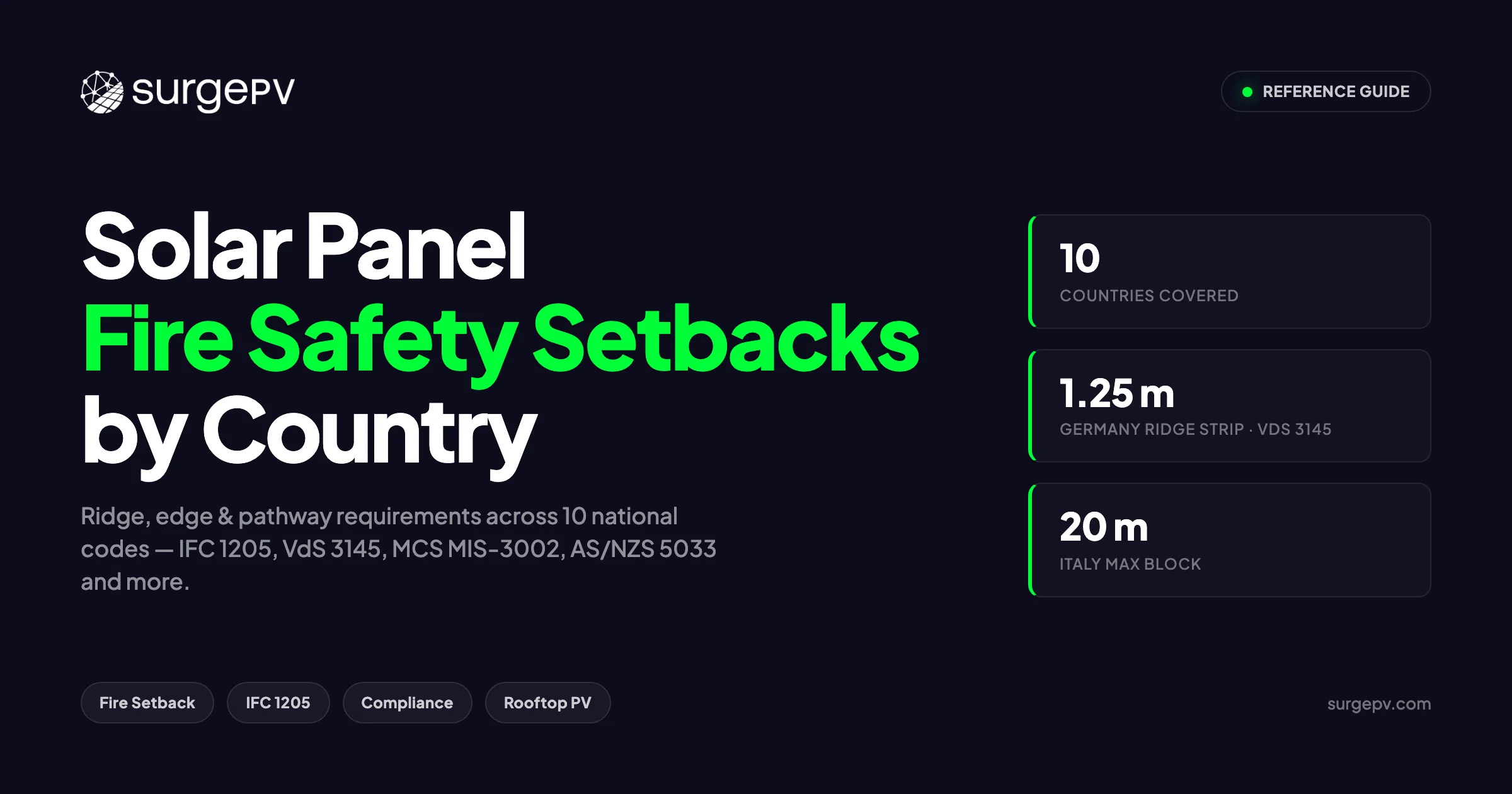
This guide is the single reference we keep open when designing across multiple geographies. It pulls the exact numbers from 10 national codes, explains why each rule is structured the way it is, and shows how solar design software can enforce the correct profile automatically rather than relying on a designer’s memory.
Every figure below comes directly from the source documents: IRC R324.6.2, IFC 1205.2.1, NFPA 1 §11.12.3, VdS 3145, MCS MIS-3002:2025, AS/NZS 5033:2021, CEA Safety Regulations 2023, Italy’s September 2025 National Fire Service guidelines, NRCan, and the Holland Solar guidelines. Source citations appear in parentheses throughout.
TL;DR
Under IRC R324.6.2 and NFPA 1 §11.12.3, US residential rooftop arrays must keep at least 18 in (457 mm) clear from both sides of the ridge when panel coverage is 33% or less of the plan-view roof area, and 36 in (914 mm) when coverage exceeds that threshold. Outside the US, requirements differ sharply: Germany’s VdS 3145 mandates a 1.25 m ridge strip; Italy’s September 2025 Fire Service rules cap panel blocks at 20 m per side with 2 m fire breaks. Always verify the adopted code edition with your authority having jurisdiction (AHJ) before finalizing any layout.
In this guide:
- Why fire setbacks exist and what each setback family — ridge, hip/valley, edge/eave, and pathway — actually measures
- Exact setback dimensions and code sources for 10 countries: US, UK, Germany, Australia/NZ, India, Italy, Spain, France, Canada, and the Netherlands
- How US residential versus commercial rules differ under IFC 1205, IRC R324.6, and NFPA 1
- Why rapid shutdown requirements interact with layout geometry, and how NEC 690.12 and CEC Rule 64-218 fit into the picture
- A single comparative table covering all 10 countries — designed for quick AHJ submission prep
- How to enforce the correct national profile inside solar design software so exclusion zones generate automatically Also see: France solar feed-in tariffs. Also see: Spain net metering. Also see: Best Solar Design Software India.
In the US, IRC R324.6.2 requires an 18 in (457 mm) clear setback from both sides of the ridge when panel coverage is 33% or less of the roof plan view, and 36 in (914 mm) when coverage exceeds 33%. Access pathways must be at least 36 in (914 mm) wide — minimum 2 per building — running from the lowest roof edge to the ridge. International rules differ: Germany requires 1.25 m at the ridge (VdS 3145); Italy limits panel blocks to 20 m × 20 m with 2 m fire breaks (Italian National Fire Service, Sept 2025).
Verify Before You Submit
The measurements below reflect the primary national or model code for each country. Adopted code editions, local amendments, and insurer conditions vary. Always confirm the current adopted code version and any local amendments with the authority having jurisdiction (AHJ) before finalizing your layout.
Why Fire Setbacks Exist
Fire setbacks are not bureaucratic friction. They solve three distinct problems that firefighters face on a roof with solar panels installed.
Firefighter access. When a structure fire drives smoke and flame upward, first responders need clear lanes to move across the roof without obstruction. Panels sitting edge-to-edge create a surface that cannot be walked safely in full gear at night or in low visibility. The IEA-PVPS Task 12 report (T12-09:2017) documents multiple incidents in Germany and the US where panel coverage prevented ladder-company access to the fire origin. A 36 in (914 mm) pathway is the minimum the ICC deems navigable with equipment.
Fire-spread containment. Panels installed over combustible roofing materials create a gap layer where fire can travel laterally without visible flame. Ridge setbacks interrupt this propagation path. Germany’s approach — a continuous 1.25 m free strip at the ridge — is designed to prevent fire from crossing from one roof plane to the other via the concealed underside of the array (VdS 3145; DGS 2011). Italy’s 20 m block rule serves the same purpose on flat commercial roofs: limit the area any single fire can reach before encountering a system-free break.
Smoke ventilation. IFC 1205.2.1 explicitly requires that arrays be “designed to provide smoke ventilation opportunity areas.” In a structure fire, trapped smoke delays ventilation and increases the risk of flashover. Ridge and edge clearances create natural draft channels that allow heat and smoke to escape before conditions deteriorate. The German firefighter schematic requirement — a mandatory site map at the junction box — exists partly so incident commanders can locate these ventilation zones without guessing.
Understanding these three purposes helps when an AHJ requests a variance or when you are designing in a country with no fixed national dimension. The argument is never “the code doesn’t say so.” The argument is always “here is how this layout provides equivalent access, containment, and ventilation.”
The 4 Setback Families Defined
Fire setback requirements fall into 4 spatial categories. Each measures something different, and a compliant layout must satisfy all 4 simultaneously.
| Setback Family | What It Measures | Governing Concept |
|---|---|---|
| Ridge | Horizontal clear distance from the roof’s peak intersection, both sides | Fire spread / smoke venting across the ridge |
| Hip/Valley | Clear distance from diagonal intersection lines on multi-plane roofs | Access to irregular roof geometry |
| Edge/Eave | Clear distance from any roof perimeter edge | Ladder placement; containment of edge-originating fires |
| Access Pathway | Width of the clear walking lane from lowest edge to ridge | Firefighter egress under live load conditions |
IFC 1205.2.1 uses the term “smoke ventilation opportunity areas” to describe the combined effect of these 4 zones. Any roof section where panels are absent becomes a potential vent zone. Ridge setbacks create the most important of these, because heat rises. Edge setbacks and pathways create secondary corridors.
A note on hip and valley setbacks: the IRC does not explicitly dimension these for residential roofs. Many local AHJs adopt specific dimensions via local amendment. For commercial buildings, IFC 1205 governs but does not specify hip/valley explicitly either — the perimeter rule functionally absorbs them on well-designed plans. Always ask your AHJ whether they have a local amendment covering hip and valley lines before submitting.
Solar design software that models 3D roof geometry can generate setback masks for all 4 families simultaneously, including diagonal hip/valley lines that are difficult to dimension manually in 2D drawings.
United States — IFC 1205, IRC R324.6, NFPA 1
The US has the most detailed published setback framework of any country in this guide, split across 3 interrelated codes: the International Residential Code (IRC), the International Fire Code (IFC), and NFPA 1. Understanding which code governs which building type prevents the most common plan-review rejections.
Residential (IRC R324.6 / NFPA 1 §11.12.3)
For Group R-3 and similar residential buildings, IRC R324.6.2 is the primary reference. The ridge setback calculation runs as follows.
Step 1. Calculate the plan-view roof area (horizontal projection, not pitched surface area).
Step 2. Calculate the total panel footprint as a percentage of that plan-view area.
Step 3. Apply the threshold:
| Coverage | Ridge Setback | With Sprinklers |
|---|---|---|
| 33% or less | 18 in (457 mm) both sides | 18 in (457 mm) — same |
| More than 33% | 36 in (914 mm) both sides | 18 in (457 mm) up to 66% / 36 in above 66% |
Source: IRC R324.6.2; NFPA 1 §11.12.3; IRC R324.6.2.1 for sprinkler exception.
Access pathways must meet all of the following (IRC R324.6.1; NFPA 1 §11.12.3):
- Minimum 2 pathways per building
- Each pathway ≥36 in (914 mm) wide
- Pathways run from the lowest roof edge to the ridge
- On separate roof planes where multiple planes exist
- At least 1 pathway on the side facing the street or driveway
Hip and valley setbacks are not explicitly dimensioned in the IRC. Always ask your AHJ whether they have a local amendment covering hip and valley lines before submitting.
Fire rating: the PV assembly must match or exceed the roof covering’s fire classification — Class A, B, or C — per UL 1703 or the newer UL 61730 (IRC R324.4).
Commercial (IFC 1205)
Commercial buildings follow IFC 1205.2.1. The rules shift from coverage-percentage thresholds to absolute perimeter and interior pathway requirements.
- Perimeter setback: 6 ft (1,829 mm) clear from all roof edges. Reducible to 4 ft on buildings with any plan dimension of 250 ft or less (IFC 1205.2.1).
- Interior pathways: required every 150 ft (45,720 mm). Each pathway is at least 4 ft (1,219 mm) wide, running in a straight line from a roof access hatch to the array perimeter or a standpipe connection. Minimum 4 ft clearance around every roof access hatch (IFC 1205.2.1).
- Smoke ventilation opportunity areas must be incorporated into the array design (IFC 1205.2.1).
Designing commercial layouts manually against this grid is error-prone at scale. Solar shadow analysis software that generates a 3D roof model can overlay the 150 ft interior pathway grid and flag zones where panels would block required access before the design is finalized.
Rapid Shutdown (NEC 690.12)
Rapid shutdown is not a setback rule, but it directly interacts with layout geometry. NEC 690.12 requires that within 30 seconds of initiating shutdown, conductors inside the array boundary fall to 80 V or less, and conductors outside the array boundary (including roof penetrations and building wiring) fall to 30 V or less. The array boundary for rapid-shutdown purposes is defined by NEC 690.12 — typically 1 ft from the module edge in current editions — not by fire setback lines. Designers should ensure that setback masks do not conflict with the placement of rapid-shutdown initiators or controlled conductors.
Top 3 AHJ Rejections for US Residential
- Wrong coverage percentage. Designers calculate pitched surface area instead of plan-view area, understating coverage and using the 18 in setback when 36 in is required.
- Missing second pathway. A single 36 in corridor is provided, but the code requires 2 — on separate roof planes.
- Hip and valley lines undimensioned. The plan shows ridge and edge setbacks but makes no reference to diagonal hip lines. AHJs with local amendments will reject this.
United Kingdom — MCS MIS-3002:2025, Approved Document B, RC62:2023
UK fire setbacks for solar are primarily a fire-class question, not a fixed-inch measurement question. The primary standards are MCS MIS-3002:2025 (domestic installations), Approved Document B (fire performance of external walls and roofs), and RC62:2023 Joint Code of Practice (commercial and industrial). For the latest details on UK, see Battery Solar System Design UK.
Residential (MCS MIS-3002:2025)
The MCS standard requires a 400 mm clear setback from any roof edge for domestic pitched-roof installations, unless wind-uplift calculations and additional fixings justify a smaller margin (MCS MIS-3002:2025 §3.9.6). The fire performance of the roof covering must not be reduced by the PV installation. In-roof kit systems need an appropriate fire-performance rating for their installed location (MCS MIS-3002:2025 §3.8.1; Approved Document B).
The fire-class framework under Approved Document B uses the European classification system from BS EN 13501-5 / CEN/TS 1187 Test 4: Also see: European Solar Incentives.
| Class | Distance from Relevant Boundary |
|---|---|
| BROOF(t4) | Unrestricted — any location on any roof |
| CROOF(t4) | Minimum 6 m from relevant boundary (England) |
| DROOF(t4) / EROOF(t4) | 6–20 m depending on building type; or bounded areas ≤3 m² with 1.5 m gaps in A2-s3,d2 rated material |
Source: Approved Document B Table B2; MCS MIS-3002:2025 Appendix A (worked example); MCS 012.
The practical implication: BROOF(t4) certified module-and-mounting combinations have no boundary-distance restriction. Combinations rated only to CROOF(t4) require the roof to sit at least 6 m from the property boundary before the array can be installed. Specifiers choosing products must confirm fire-class certification applies to the complete assembly — module, mounting rail, and roof interface — not just the panel alone. See Solar Racking Design Guide for detailed guidance.
A DC isolator or load-break disconnection device must be provided per BS 7671 Part 7-712, either external to the building or housed in a fire-resistant enclosure (MIS-3002:2025; IET Code of Practice).
When generating UK solar proposal software outputs, include the BROOF(t4) certification reference for the specific product assembly on the design summary page — insurers and AHJs increasingly require it.
Commercial and Industrial (RC62:2023)
RC62:2023 — the Joint Code of Practice published by RISCAuthority, MCS, and Solar Energy UK — governs larger commercial and industrial installations. It requires a risk assessment covering compartmentalization, maintenance planning, and insurer consultation. Access walkways are required around the array perimeter. Larger arrays must be subdivided into smaller blocks with access corridors between them (MCS MIS-3002:2025 §3.6.2). The specific dimensions come from the risk assessment rather than fixed prescriptions — the designer and the insurer’s fire surveyor agree them jointly.
Germany — VdS 3145, DGS, VDE-AR-E 2100-712
Germany’s fire setback system sits primarily in VdS 3145 — a guideline published by VdS Schadenverhütung, the German insurer association — and the DGS 2011 installer guidelines. VdS 3145 is not a legal mandate; it is an insurer recommendation that has become the de facto industry standard because non-compliance creates liability exposure and policy voidance risk. The DIN VDE 0100-712 and VDE-AR-E 2100-712 standards govern the electrical safety side.
Pitched Roofs
For pitched residential and commercial roofs, VdS 3145 specifies:
- Ridge setback: 1.25 m continuous free strip running the full building length at the ridge, both sides
- Edge/verge setback: 0.5 m from all roof edges and verges where fire brigade ladders may be placed
- Skylight/vent clearance: 0.5 m on all sides of any penetration
- Access pathway: 1.0–1.25 m continuous lane from any roof-access point to each array section
Source: VdS 3145; SMA whitepaper citing DGS 2011.
The 1.25 m ridge strip is wider than any US residential requirement. German fire-service guidance (IEA-PVPS T12-09:2017) shows this as a direct response to fires where the panel-cavity gap allowed flames to travel across the ridge into the adjoining roof plane.
Flat Roofs
Flat-roof commercial installations in Germany follow the DGS 2011 framework, which divides the roof into fire compartments:
- Compartment maximum: 40 m × 40 m
- Access lanes around each compartment: ≥1 m wide
- For smaller roofs with no interior access, a free strip on the longer building side provides roof-truss access for the fire brigade
Source: DGS 2011 guidelines; IEA-PVPS T12-09:2017 Table 3.3.
DC Wiring and Firefighter Documentation
DC cables inside the building must either route through fire-protected conduit rated at minimum F30 or run outside the building envelope entirely (VDE-AR-E 2100-712; DIN VDE 0100-712). They must be labeled as fire-resistant wiring throughout their run.
A firefighter schematic is mandatory: a diagram posted at the junction box or distribution board showing the premises layout, conductor runs, and all disconnection points. The German Firefighters Association requires this diagram to be current and accessible without tools.
Firefighting water should be applied from no less than 1 m using a spray jet or no less than 5 m using a full jet to avoid electrocution risk on energized DC conductors (DIN 14365-CM / VDE 0132, cited in Högskolan Dalarna research).
Select the Germany (VdS 3145) profile in solar design platform to auto-generate 1.25 m ridge masks and 40 m × 40 m compartment grids on flat roofs.
Australia and New Zealand — AS/NZS 5033:2021
Australia and New Zealand present a structural difference from every other country in this guide: their primary solar electrical standard — AS/NZS 5033:2021 — does not specify geometric fire setbacks. Ridge clearances, edge margins, and pathway widths fall under the National Construction Code / Building Code of Australia (NCC/BCA) and local fire regulations, not the electrical standard. Designers working in Australia and New Zealand must consult both documents.
AS/NZS 5033:2021 does contain several safety provisions that interact with fire risk:
| Parameter | Requirement | Source |
|---|---|---|
| Max DC voltage (domestic) | 1,000 V | AS/NZS 5033:2021 §3.1 |
| Max DC voltage (non-domestic) | 1,500 V | AS/NZS 5033:2021 §3.1 |
| Disconnection point location | ≤150 mm from module edge; positive and negative together; labeled within 300 mm; signage required | AS/NZS 5033:2021 §4.3.5.2.1 |
| Ceiling-space cable routing | Secured; ≥0.6 m above ceiling surface unless within 1.5 m of internal surface of external wall | AS/NZS 5033:2021 §4.4.5.2.3 |
| Minimum conductor size | 4 mm² for all PV DC cables (compulsory) | AS/NZS 5033:2021 §4.4.2.3 |
| Fire/emergency info sign | Required at main switchboard; shows isolation method and system layout | AS/NZS 5033:2021 §5.4 |
The disconnection point rule — ≤150 mm from module edge — is positioned to minimize the energized conductor run that a firefighter would encounter when ventilating the roof. The 2021 revision replaced the blanket rooftop DC isolator requirement with a more targeted approach: for 1–2 string systems without string fusing, a non-load-break connector serves as the disconnection point; for systems with more than 2 paralleled strings with fusing, a load-break disconnection is required (AS/NZS 5033:2021 §4.3.3; CEC Advice on AS/NZS 5033).
Australian design software must model disconnection-point locations, enforce the 4 mm² minimum cable size, and generate the mandatory site-layout sign (AS/NZS 5033:2021 Figure A.5). Ridge setbacks, where required, come from the NCC/BCA overlay applicable to the specific state and building class.
India — CEA Safety Regulations 2023, MNRE Specs
India’s solar fire safety framework is defined by the Central Electricity Authority (CEA) Safety Regulations 2023 and MNRE technical specifications. The framework is strong on access and electrical protection but does not codify a fixed national ridge setback dimension. For the latest details on India, see 5kW Solar Panel Price in India.
| Parameter | Requirement | Source |
|---|---|---|
| Roof-access pathway | Minimum 75 cm with handrails for roof access and emergency exit | CEA Safety Regulations 2023 |
| Inter-row walkways | Clear pathways between all rows and columns for cleaning and maintenance | CEA Safety Regulations 2023 |
| Ridge setback | No national fixed dimension — local fire services and state building codes may impose distances | SWE/SHPV module manual; NBC 2016 Part 4 |
| Fire detection/suppression | Fire detection and automatic suppression systems shall comply with relevant standards | CEA Safety Regulations 2023 |
| DC isolator | Load-breaking; independent manual operation; non-polarity-sensitive; rated to interrupt full load and fault currents; installed in accessible area | MNRE technical specs; CEA 2023 |
| DC cable protection | No exposed cables on roof; protected from physical damage; cable trays lidded; bridges over pathways | MNRE technical specs |
| Ground-mount fencing | ≥1.8 m height to prevent unauthorized entry | CEA Safety Regulations 2023 |
| Earthing | 3 separate earth pits: DC side, AC side, lightning arrestor; earth resistance ≤5 ohms | MNRE specs; IS 3043:2018 |
The absence of a national ridge setback does not mean the dimension is optional. Local fire officers in Maharashtra, Karnataka, Rajasthan, and other major solar states routinely impose site-specific clearances during NOC review. The practical approach is to design to a conservative 75 cm ridge margin as a baseline and document it explicitly in the submission — this satisfies most fire officers without requiring a variance.
Indian designs must guarantee 75 cm minimum access paths with handrails throughout. Because the national ridge setback is not codified in CEA/MNRE documents, cloud solar design tool should flag “consult local fire officer” for ridge proximity on Indian projects.
Italy — September 2025 National Fire Service Rules
Italy introduced binding national fire safety rules for PV systems in September 2025. The Italian National Fire Service (Vigili del Fuoco) guidelines are specific, numerically precise, and the most recently updated national framework of any country in this guide.
| Parameter | Requirement | Source |
|---|---|---|
| Panel group max dimension | 20 m per side (applies both directions) | Italian National Fire Service guidelines, Sept 2025 |
| System-free separation between groups | 2 m | Italian National Fire Service guidelines, Sept 2025 |
| Roof edge strip | 1 m clear strip | Italian National Fire Service guidelines, Sept 2025 |
| Vent/skylight/chimney clearance | ≥1 m | Italian National Fire Service guidelines, Sept 2025 |
| Inverter/ventilation compartments | REI/EI 30 rated | Italian National Fire Service guidelines, Sept 2025 |
| Structure and materials | Non-combustible (Class A1) or EI 30 | Italian National Fire Service guidelines, Sept 2025 |
| Panel fire reaction | Class E per EN 13501-1 (EN ISO 11925-2 small flame test); or CEI TS 82-89 combined-system test (BFV–EFV rating) | Istituto Giordano / CEI TS 82-89; 2025 Fire Brigade guidelines |
| Maintenance | Biennial fire-risk inspections | Italian National Fire Service guidelines, Sept 2025 |
| Exemptions | Ground-mount, systems under 800 W, agrivoltaic installations more than 100 m from buildings | pv magazine Italy, Sept 2025 |
The 20 m × 20 m block rule is the defining constraint for Italian commercial design. A 60 m × 30 m flat-roof array must be divided into blocks no larger than 20 m per side, with 2 m system-free lanes between them. That means a 60 m run requires at least 2 internal fire breaks of 2 m each, reducing net array length to approximately 56 m. On wide roofs the arithmetic has a material impact on kWp capacity estimates.
The biennial fire-risk inspection requirement is new and has operational implications: maintenance contracts for Italian commercial installations must now budget for formal fire assessments every 2 years.
Spain, France, Canada, and the Netherlands
These 4 markets share a common characteristic: national fire setback dimensions are either not codified or are locally determined. The design default for each is set by industry guidelines, municipal regulations, or insurer conditions rather than a single binding national standard.
Spain
Spain’s primary electrical regulation for PV is REBT ITC-BT-40, with a newer ITC-BT-53 under development based on HD 60364-7-712. Neither standard specifies geometric setbacks. Fire clearances are set by local bomberos (municipal fire services) and municipal ordinances. For installations above 25 kW or in public premises, initial third-party inspection is required; periodic inspections typically follow every 5 years for systems above certain power thresholds. A manual general DC disconnect switch, identifiable and accessible, is required under REBT ITC-BT-40.
The default practice in Spain is a conservative 1 m edge clearance, applied consistently until local bomberos confirm a different requirement in writing. Designers should document the 1 m default and include a cover letter noting that formal fire-service consultation has been requested.
France
France is decentralized by design: setback rules are governed by the Plan Local d’Urbanisme (PLU) of each commune. The typical values seen in practice are a 60 cm lateral access pathway and a 50 cm edge setback (SurgePV Europe fire-safety guide; K2 Systems France ETN). These are guidelines, not fixed law. Actual requirements are determined by the PLU and, for ERP buildings (établissements recevant du public), by the fire brigade and central safety commission under the arrêté du 25 juin 1980 (articles EL). ERP installations require fire brigade consultation and validation before energization. For France-specific information, see Agricultural Solar Case Study. See Solar Sales Commission Structure for detailed guidance.
DC isolation requires a lockable visible disconnect at ground level with automatic inverter shutdown on grid loss (UTE C 15-712-1).
Canada
NRCan’s Photovoltaic Ready Guidelines identify 18–36 in (457–914 mm) as best-practice ridge setbacks — not a federal mandate. Pathway requirements follow the same range: two 18–36 in corridors from ridge to eave on gable roofs; one 18–36 in corridor per slope on hip roofs, potentially split across the hip. No federal uniform setback is legislated (NRCan Photovoltaic Ready Guidelines).
Rapid shutdown is codified. CEC Rule 64-218 requires conductors to de-energize to 30 V or less within 30 seconds when conductors run more than 1 m from the array (CEC Rule 64-218; Ontario ESA Bulletin 64-6-1). Module and mounting combinations are evaluated per CAN/ULC-S1703 or UL 1703 for fire rating (Canadian Solar / CSI installation manuals). Municipal amendments exist — Alberta’s STANDATA 18-ECV-064-218 provides a variance on rapid-shutdown initiator marking requirements. For Canada-specific compliance details, see Canada comparisons/solar-design-software.
Netherlands
Holland Solar’s industry guidelines specify a 50 cm edge setback and a 90 cm access pathway as defaults (Holland Solar guidelines; SurgePV Europe guide). Neither figure is national law. The electrical installation standard is NEN 1010:2020, with NEN-EN 50549-1 covering grid connection. Municipal building permits and insurer conditions are the operative enforcement mechanisms — and they increasingly specify setbacks explicitly as a condition of coverage. SCIOS Scope 12 is the applicable electrical-safety inspection protocol for PV systems. For a direct comparison, see Arka 360 vs SurgePV.
solar software supporting Netherlands projects should apply the Holland Solar 50 cm/90 cm defaults with an override field for insurer-specific conditions.
| Country | Primary Standard | Default Setbacks |
|---|---|---|
| Spain | REBT ITC-BT-40 | 1 m edge (common practice); no national fixed ridge |
| France | PLU (commune-level) + UTE C 15-712-1 | 60 cm pathway, 50 cm edge typical |
| Canada | NRCan best-practice + CEC 64-218 | 18–36 in ridge, 18–36 in pathway |
| Netherlands | Holland Solar + NEN 1010:2020 | 50 cm edge, 90 cm pathway |
Country Comparison Master Table
The table below consolidates the key dimensions from all 10 countries. Use it for AHJ submission prep and multi-country project scoping. Confirm the adopted code edition with each local AHJ before finalizing — local amendments take precedence.
| Country | Code / Standard | Ridge Setback | Edge Setback | Pathway Width | Commercial Rule | Rapid Shutdown | Fire Rating | National Std? |
|---|---|---|---|---|---|---|---|---|
| US | IRC R324.6.2; IFC 1205; NFPA 1 §11.12.3 | 18 in (≤33% coverage) / 36 in (>33%) | Not universally codified (residential); 6 ft perimeter (commercial) | 36 in (residential); 4 ft (commercial) | 6 ft perimeter; 4 ft pathways every 150 ft | NEC 690.12: ≤80 V inside / ≤30 V outside, 30 s | Class A/B/C per UL 1703 / UL 61730 | Yes |
| UK | MCS MIS-3002:2025; AD B; RC62:2023 | Not dimensioned separately — fire-class distances govern | 400 mm (domestic pitched) | Perimeter walkway (C&I, size by risk assessment) | RC62:2023 risk assessment; corridor subdivision | DC isolator per BS 7671 Part 7-712 | BROOF(t4) preferred; CROOF(t4) ≥6 m from boundary | Yes |
| Germany | VdS 3145; DGS 2011; VDE-AR-E 2100-712 | 1.25 m (both sides of ridge) | 0.5 m | 1.0–1.25 m | 40 m × 40 m grid, 1 m lanes | VDE-AR-E 2100-712 (system shutdown) | F30 DC cable routing; firefighter schematic mandatory | Insurer guideline |
| Australia / NZ | AS/NZS 5033:2021 + NCC/BCA | NCC/BCA governs (not in AS/NZS 5033) | NCC/BCA governs | NCC/BCA governs | NCC/BCA + state regs | AS/NZS 5033:2021 §4.3.3 disconnection point | Emergency info sign; 4 mm² DC cable | Yes (electrical) |
| India | CEA Safety Regs 2023; MNRE specs | No national fixed dimension | No national fixed dimension | 75 cm with handrails | CEA 2023 inter-row walkways | Load-break DC isolator (CEA 2023) | Fire detection + suppression required | Yes |
| Italy | Italian National Fire Service, Sept 2025 | N/A (block size rule instead) | 1 m clear strip | 2 m system-free separation between blocks | 20 m × 20 m max block, 2 m breaks | N/A | Class E per EN 13501-1; REI/EI 30 compartments | Yes (binding) |
| Spain | REBT ITC-BT-40 | No national fixed dimension | 1 m common practice | 1 m common practice | Local bomberos | Manual DC disconnect (REBT ITC-BT-40) | Varies by municipality | No |
| France | PLU + UTE C 15-712-1 | No national fixed dimension | 50 cm typical | 60 cm typical | ERP: fire brigade consultation required | Lockable ground-level DC disconnect (UTE C 15-712-1) | Preserves roof covering fire rating | No |
| Canada | NRCan guidelines; CEC Rule 64-218 | 18–36 in (best practice, not mandated) | Local AHJ | 18–36 in per slope | Local AHJ | CEC Rule 64-218: ≤30 V, 30 s | CAN/ULC-S1703 or UL 1703 | Best practice |
| Netherlands | Holland Solar + NEN 1010:2020 | No national fixed dimension | 50 cm (Holland Solar) | 90 cm (Holland Solar) | Insurer conditions | NEN 1010:2020 | SCIOS Scope 12 inspection | Guideline |
Designing Across Multiple Markets?
SurgePV applies the correct fire-setback profile for each country as a dynamic exclusion mask — so your layout starts compliant, not just close.
Book a DemoNo commitment required · 20 minutes · Live project walkthrough
How to Enforce Fire Setbacks in Solar Design Software
Why Manual Checks Fail at Scale
A multi-market EPC running 20 projects simultaneously across Germany, the UK, and the US is managing 3 different setback logic systems. The German projects need 1.25 m ridge strips and 40 m compartment grids. The US residential projects need a coverage-percentage calculation that changes the ridge dimension. The UK projects need BROOF(t4) boundary distances layered over a 400 mm edge margin. Manual checks in 2D CAD drawings miss intersecting constraints — a layout that passes the ridge check can still fail because a pathway is blocked by a service hatch, or because a compartment grid wasn’t extended to cover a roof annexe.
Design errors caught at permit review cost more than the time to fix them. A typical US residential plan-review revision takes 10–14 business days. In Germany, an insurance inspection rejection delays energization by weeks.
5-Step Workflow in SurgePV
Step 1 — Select the national profile. Choose the country from the project settings. The software loads the appropriate setback logic: coverage-percentage thresholds for the US, fixed-meter masks for Germany and Italy, boundary-distance tables for the UK.
Step 2 — Auto-mask the roof. The 3D roof model generates non-editable exclusion zones for all 4 setback families — ridge, hip/valley, edge/eave, and pathways. Panels cannot be placed within these zones.
Step 3 — Calculate live coverage percentage. For US projects, the software calculates plan-view coverage dynamically as panels are added, switching the ridge setback mask from 18 in to 36 in at the 33% threshold in real time.
Step 4 — Flag violations. Any placement that would violate a setback — an access hatch too close to a panel row, a smoke-vent clearance breached by a module corner — appears as a flagged error before export.
Step 5 — Export the compliant layout. The exported plan set includes dimensioned setback annotations, the coverage-percentage calculation (for US), and the applicable code citation for each setback zone. For UK projects, the BROOF(t4) product certification reference auto-populates from the module database.
For financial modeling of layouts constrained by fire setbacks, the generation and financial tool updates yield and revenue projections as the compliant array area is confirmed — so the client sees actual generation capacity after setbacks are applied, not a theoretical maximum.
Clara AI, SurgePV’s design assistant, can generate permit notes explaining each setback dimension and its code source — formatted for the specific AHJ’s submission requirements. This removes the manual step of annotating why each clearance exists.
For large commercial layouts under IFC 1205, the 150 ft interior pathway grid is not just a perimeter check. The software maps the full grid, placing pathway corridors at the required intervals and adjusting panel rows to maintain the 4 ft clear width throughout, not only at the edges.
Common AHJ Rejections and How to Avoid Them
The following table consolidates the most frequent rejection types across the 10 countries in this guide.
| Rejection | Root Cause | Fix |
|---|---|---|
| Wrong coverage-% ridge dimension (US) | Designer used pitched surface area instead of plan-view area to calculate coverage, understating the percentage | Always use the horizontal projection (plan view) of the roof for the coverage calculation, not the actual sloped area |
| Missing second access pathway (US residential) | Only 1 pathway provided; code requires at least 2 on separate roof planes (IRC R324.6.1) | Place pathways on separate roof planes; annotate each pathway as “Pathway 1 — street side” and “Pathway 2 — adjoining plane” |
| Hip/valley lines undimensioned | Plan shows ridge and edge setbacks but no setback annotation at diagonal intersections | Add explicit annotations at every hip and valley line per local AHJ requirements; include a detail callout noting the local amendment reference |
| BROOF(t4) not confirmed (UK) | Module fire-class certification is for the panel only — not the complete assembly on the specific roof substrate | Order complete-assembly test certification from the mounting-system manufacturer; confirm substrate compatibility before submission |
| German ridge setback undersized (1.0 m vs 1.25 m) | Older references cite 1.0 m; VdS 3145 specifies 1.25 m as the current recommendation | Use 1.25 m in all German designs; note that 1.0 m may be accepted by some insurers but creates coverage risk |
| Italy block exceeds 20 m | Designer sized the block for maximum coverage without applying the Italian National Fire Service (Sept 2025) 20 m dimension cap | Divide long arrays into blocks ≤20 m per side; place 2 m system-free separation between all groups; annotate block dimensions on plan |
| India handrails missing on access pathway | 75 cm pathway exists but handrail specification absent from structural detail | Add handrail detail to the roof access section of the drawing set; reference CEA Safety Regulations 2023 in the title block |
Pre-Submission Compliance Checklist
Use this checklist before submitting any solar plan for permit review. Each item maps to a specific code citation.
US Residential
- Plan-view roof area calculated (not sloped area) and coverage percentage documented
- Ridge setback: 18 in if ≤33% coverage; 36 in if >33% coverage (IRC R324.6.2)
- Sprinkler status documented if using reduced-setback exception (IRC R324.6.2.1)
- Minimum 2 access pathways, each ≥36 in wide, on separate roof planes (IRC R324.6.1)
- At least 1 pathway on the street- or driveway-facing slope
- Hip and valley setbacks annotated per local AHJ requirement
- Fire classification: module assembly confirmed Class A/B/C per UL 1703 or UL 61730 (IRC R324.4)
- Rapid shutdown initiator location labeled on plan (NEC 690.12)
US Commercial (IFC 1205)
- 6 ft (or 4 ft for plan dimension ≤250 ft) perimeter setback shown on all roof edges (IFC 1205.2.1)
- Interior pathways at maximum 150 ft spacing, each ≥4 ft wide, straight-line to standpipes (IFC 1205.2.1)
- 4 ft clearance around all roof access hatches
- Smoke ventilation opportunity areas identified and annotated
- Rapid shutdown equipment placement coordinated with array layout (NEC 690.12)
United Kingdom
- Edge setback: ≥400 mm from all roof edges unless wind calculations justify otherwise (MCS MIS-3002:2025 §3.9.6)
- Complete assembly fire class confirmed: BROOF(t4) preferred; if CROOF(t4), confirm building is ≥6 m from relevant boundary (AD B)
- DC isolator external to building or in fire-resistant enclosure, per BS 7671 Part 7-712
- For C&I: RC62:2023 risk assessment completed; insurer notified; access corridors shown on plan
Germany
- Ridge free strip: ≥1.25 m continuous both sides, full building length (VdS 3145)
- Edge/verge setback: ≥0.5 m (VdS 3145)
- Pathway: ≥1.0–1.25 m from roof access point to each array section
- Flat roof: 40 m × 40 m compartment grid drawn; 1 m access lanes shown around each block
- Skylight/vent clearance: ≥0.5 m on all sides
- DC cable routing: F30 fire protection or external routing confirmed (VDE-AR-E 2100-712)
- Firefighter schematic posted at junction box/distribution board
Italy
- Each panel block dimensioned ≤20 m per side (Italian National Fire Service, Sept 2025)
- 2 m system-free separation between all panel groups shown on plan
- 1 m roof edge strip maintained on all edges and around vents/chimneys
- Inverter and ventilation compartments rated REI/EI 30
- Panel fire reaction class: Class E per EN 13501-1 or CEI TS 82-89 combined-system test confirmed
- Biennial fire-risk inspection schedule noted in O&M documentation
Australia and New Zealand
- Disconnection point(s) located ≤150 mm from module edge, labeled within 300 mm (AS/NZS 5033:2021 §4.3.5.2.1)
- DC cable minimum 4 mm² confirmed throughout (AS/NZS 5033:2021 §4.4.2.3)
- Ceiling-space cables ≥0.6 m above ceiling surface unless within 1.5 m of internal surface of external wall (AS/NZS 5033:2021 §4.4.5.2.3)
- Emergency info sign content confirmed for main switchboard (AS/NZS 5033:2021 §5.4)
- NCC/BCA geometric setbacks confirmed with local authority (not covered by AS/NZS 5033)
India
- 75 cm minimum access pathways with handrails confirmed throughout roof area (CEA Safety Regulations 2023)
- Inter-row walkways clear for cleaning and maintenance
- Fire detection and automatic suppression system specified
- DC cable protection: no exposed cables; trays lidded; pathway bridges in place (MNRE specs)
- 3 earth pits (DC side, AC side, lightning arrestor) each ≤5 ohms (IS 3043:2018)
- Local fire officer consulted for ridge setback requirement (no national standard)
Canada, Spain, France, and Netherlands
- Canada: NRCan best-practice setback (18–36 in) applied and documented; CEC Rule 64-218 rapid shutdown boundary modeled; local AHJ variance confirmed
- Spain: 1 m edge clearance applied as default; local bomberos consultation request documented; ITC-BT-40 manual DC disconnect confirmed
- France: PLU requirements confirmed with commune; 60 cm pathway and 50 cm edge minimum applied; for ERP buildings, fire brigade consultation completed (arrêté du 25 juin 1980); UTE C 15-712-1 DC isolation confirmed
- Netherlands: Holland Solar 50 cm edge / 90 cm pathway applied; insurer-specific setback conditions reviewed; SCIOS Scope 12 inspection scheduled post-installation
Conclusion
Fire setback compliance is a design-stage problem, not a permit-stage problem. Every country in this guide anchors its requirements to the same 3 principles (firefighter access, fire-spread containment, and smoke ventilation), but expresses them in incompatible units and logic systems. The designer who treats setbacks as an afterthought will redesign. The designer who builds them in from the first panel placement completes the layout once.
Three things to do before your next submission:
- Confirm the adopted code edition with the AHJ — not the model code, not last year’s version. US jurisdictions can lag 1–2 code cycles; Italy’s September 2025 rules are new enough that some local fire offices have not yet updated their submission checklists.
- Use coverage-percentage logic for US residential, block-size logic for Italy, and compartment-grid logic for Germany flat roofs — these are three different calculations. Applying the wrong one is the root cause of most plan-review rejections.
- Let solar shadow analysis software generate the setback exclusion zones before you place a single panel — starting with the exclusion mask forces you to design within constraints, rather than retrofitting clearances into a layout that already fills the roof.
Getting the setback right at the layout stage costs nothing. Getting it wrong at permit costs two weeks and a redesign.
One Layout Tool, Every Country’s Rules
Select your country profile in SurgePV and fire-setback exclusion zones generate automatically across the 3D roof model.
Book a DemoNo commitment required · 20 minutes · Live project walkthrough
Frequently Asked Questions
What is the standard fire setback for solar panels?
In the US, IRC R324.6.2 and NFPA 1 §11.12.3 require 18 in (457 mm) from both sides of the ridge when panel coverage is 33% or less of the plan-view roof area, and 36 in (914 mm) when coverage exceeds 33%. Access pathways must be at least 36 in (914 mm) wide. Outside the US, rules differ sharply: Germany’s VdS 3145 mandates a 1.25 m ridge strip; Italy caps individual panel blocks at 20 m per side with 2 m fire breaks between them. There is no single universal standard — always confirm requirements with the authority having jurisdiction.
Do solar panels need a 3-foot setback?
The 3-foot (36 in / 914 mm) figure appears in two places under US residential codes: ridge setbacks when panel coverage exceeds 33% of the roof’s plan-view area, and the minimum width for every access pathway. Some commercial codes also require 3 ft perimeter clearances. In Germany, the 1.25 m ridge requirement is slightly larger than 3 ft. Always check the adopted code edition with your local AHJ — 3 ft is a US benchmark, not a universal standard.
What is IFC 1205 for solar?
IFC 1205 is Section 1205 of the International Fire Code governing rooftop photovoltaic systems. It specifies access pathways, setback zones, and smoke ventilation opportunity areas designed to enable firefighter operations on roofs with solar installed. For commercial buildings it requires a 6 ft (1,829 mm) clear perimeter — reducible to 4 ft on buildings with a plan dimension of 250 ft or less — plus interior pathways every 150 ft that are at least 4 ft (1,219 mm) wide. Residential rules fall primarily under IRC R324.6.
Are fire setbacks for solar required in Europe?
There is no single EU-wide setback regulation. Each country maintains its own framework. Germany’s VdS 3145 insurer guideline specifies 1.25 m at the ridge and a 40 m × 40 m compartment grid for flat roofs. Italy’s National Fire Service issued binding rules in September 2025 capping panel blocks at 20 m per side with 2 m fire breaks. The UK requires BROOF(t4) fire-class compliance under Approved Document B with distance-from-boundary tables. France and the Netherlands rely on locally determined setbacks without a binding national dimension.
How do you calculate the correct solar fire setback?
The calculation method depends on the country. In the US, measure the total plan-view roof area, then calculate panel coverage as a percentage — 33% or less gives an 18 in ridge setback; above 33% requires 36 in. For commercial US projects, map a 6 ft perimeter and place interior pathways every 150 ft. In Germany, divide the flat roof into 40 m × 40 m compartments and leave 1 m lanes around each. In Italy, keep each panel block under 20 m × 20 m and place 2 m system-free breaks between groups. In the UK, identify the assembly’s BROOF(t4) classification and check boundary-distance tables from Approved Document B.
Can solar design software automatically apply fire setbacks?
Yes. Modern SurgePV’s design suite can apply country-specific setback profiles as dynamic exclusion masks on the 3D roof model, preventing panels from being placed in protected zones. SurgePV allows you to select a national profile — such as Germany VdS 3145 or US IFC 1205 — and the software automatically generates ridge strips, edge clearances, access pathway corridors, and compartment grids. The coverage-percentage calculation for US residential projects updates in real time as panels are added, switching the ridge mask automatically at the 33% threshold. This eliminates manual calculation errors and produces a layout ready for AHJ submission.