Quick Answer
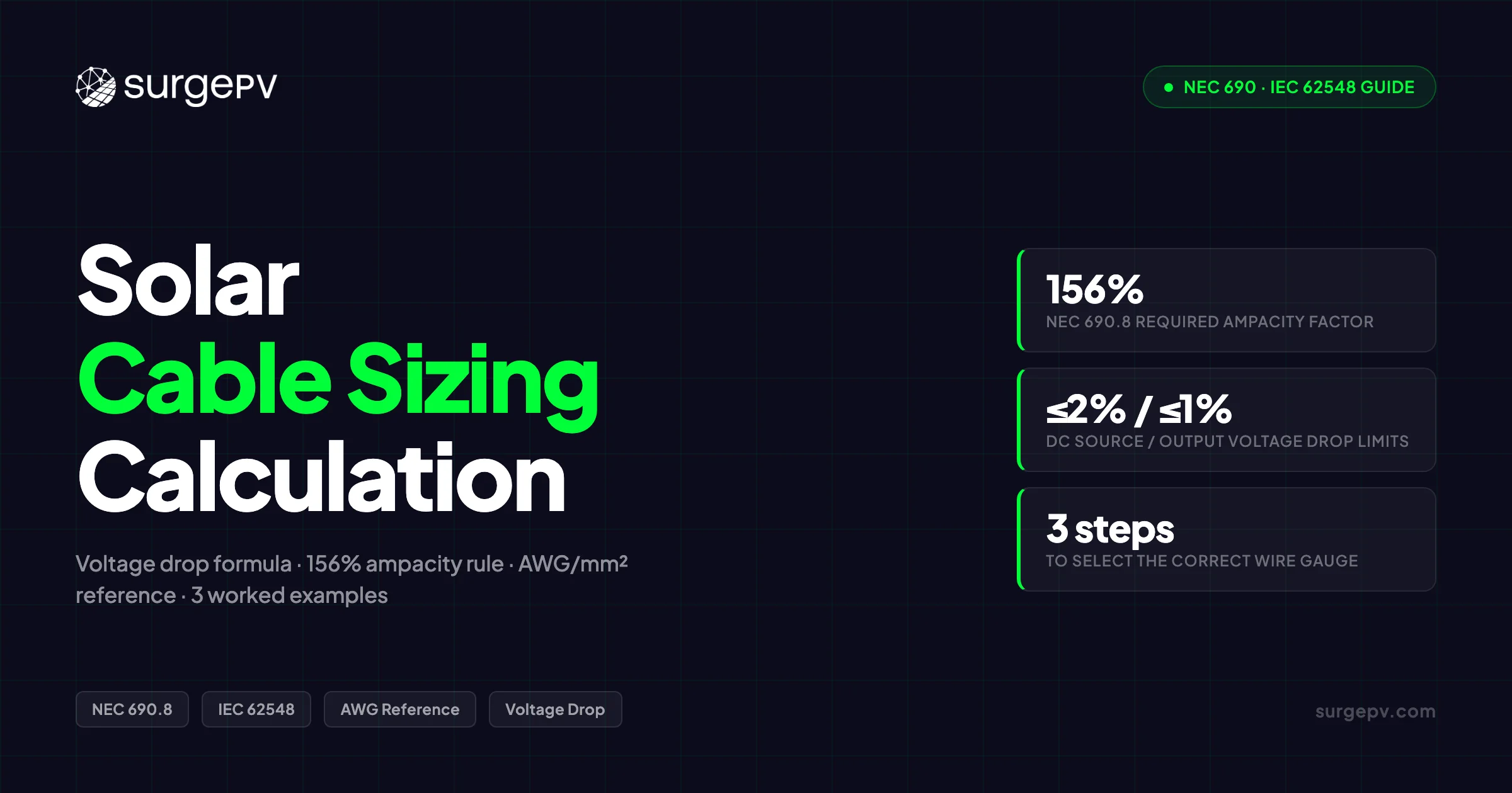
Solar cable sizing follows three steps: calculate circuit current (Isc × 1.25 for DC), apply temperature derating factors from NEC 310.16, and verify voltage drop under 2% for DC and 3% for AC. Common sizes: 10 AWG for residential strings, 8 AWG for commercial, and 4/0 AWG for main feeders.
Cable sizing errors are the leading cause of AHJ plan-check rejections on solar permit sets. Most guides give you one formula and one 125% multiplier, then leave you to figure out the rest. The result: conductors that pass the desk calculation and fail inspection because the designer skipped the second 125%, forgot to derate for a 45°C rooftop conduit, or used operating current (Imp) instead of short-circuit current (Isc) as the sizing basis.
Solar cable sizing follows three steps: calculate circuit current (Isc × 1.25 for DC), apply temperature derating factors from NEC 310.16, and verify voltage drop under 2% for DC and 3% for AC. Common sizes: 10 AWG for residential strings, 8 AWG for commercial, and 4/0 AWG for main feeders.
This guide covers the full calculation in the order you would actually run it: NEC 690.8 ampacity rules (including the correct two-step 156% multiplier), IEC 62548 voltage-drop limits, temperature and conduit derating, three fully worked examples for residential and commercial systems, and a reference AWG/mm² table mapped to real PV applications. We also show where solar design software handles every step automatically and flags violations before you export the permit set.
TL;DR — Solar Cable Sizing
Under NEC 690.8, every PV source circuit conductor must carry 156% of the string’s rated Isc — not Imp, not 125%. IEC 62548 allows a 3% total voltage drop vs. NEC’s 2%/1% split. Select cable cross-section using A = (2 × L × I × ρ) / ΔV, then apply combined temperature and conduit derating before locking in the final AWG or mm² size.
In this guide:
- Why the NEC 690.8 two-step calculation produces 156% of Isc — and what happens when you only apply one multiplier
- The DC voltage-drop formula and NEC vs. IEC limits side by side
- How to apply temperature derating and conduit bundling together in one calculation
- A complete AWG/mm² reference table with typical PV circuit applications
- The bifacial module “highest Isc” requirement under NEC 690.8(A)(1)(a)(1)
- Three worked examples: residential 6.6 kW string, commercial 100 kW combiner-to-inverter run, and a combined derating scenario
- How solar design software auto-calculates all of this and flags violations before permit submission Read Bifacial Solar Panel Design Guide for a complete walkthrough.
Why Cable Sizing Errors Cause Real Project Failures
Four calculation errors account for the majority of cable sizing rejections and field failures on PV installations:
- Sizing to Imp instead of Isc. The maximum power current and the short-circuit current differ by 5–10% on most crystalline silicon modules. That gap grows when you apply two 125% multipliers on top of it.
- Applying only one 125% multiplier. NEC 690.8 requires the factor applied twice — once in subsection (A) to establish the maximum circuit current, and again in subsection (B) to establish the required conductor ampacity.
- Ignoring conduit bundling. Four circuits sharing a conduit reduces each conductor’s rated ampacity by 20% before temperature correction is even applied.
- Reading from the 60°C ampacity column. NEC 690.31(C) mandates 90°C-rated conductors for PV source circuits. Using the 60°C column for a USE-2 or PV Wire conductor leaves real ampacity on the table and produces an unnecessarily large cable size.
Here is what a compound error looks like in practice. A designer sizes a residential 10 kW system at 12 AWG (3.3 mm²) using the 90°C free-air ampacity of 30 A. At the desk, 30 A clears the 14.84 A required ampacity from the correct 156% calculation — and it does. But the cable runs in a conduit with five other current-carrying conductors at 45°C ambient. Temperature correction drops the factor to 0.87; conduit bundling drops it further to 0.80. Combined factor: 0.696. Adjusted ampacity: 30 × 0.696 = 20.9 A. Required: 14.84 A. The conductor still passes — barely — on the (B)(1) path. But under (B)(2), which requires the adjusted ampacity to meet the maximum circuit current after site conditions, the picture is tighter. And if the actual conduit temperature spikes to 50°C in July, the factor falls to 0.82 × 0.80 = 0.656, giving 19.7 A — which does fail.
The Most Common Mistake
Designers pull Imp from the datasheet and treat it like Isc. These values differ by 5–10% on most panels — and that gap compounds through the two-step 125% multiplier. On a system where Isc is 9.5 A and Imp is 8.9 A, using Imp produces a required ampacity of 13.91 A instead of the correct 14.84 A — a difference of nearly 7%.
The Two Cable Sizing Jobs: Ampacity vs. Voltage Drop
Cable sizing for PV systems involves two separate checks that both constrain the final cable size. Many guides conflate them; treating them as one calculation is what produces cables that pass on paper but fail in the field.
| Check | Governs | Standard | Limit |
|---|---|---|---|
| Ampacity | Conductor temperature and safety | NEC 690.8(B) | ≥ 156% of Isc (or site-derated equivalent) |
| Voltage Drop | Energy yield and efficiency | NEC informational / IEC 62548 | ≤ 2% source, ≤ 1% output (NEC); ≤ 3% total (IEC) |
A cable can pass the ampacity check and fail the voltage-drop check, or pass voltage drop and fail ampacity. You run both, then select the larger resulting size.
The constraint that governs depends on run length. On string runs under 20 m, ampacity almost always governs — the voltage drop across a short run is negligible. On combiner-to-inverter homeruns over 40 m, voltage drop almost always governs — the resistive loss over a long run requires a larger conductor than ampacity alone would mandate. Know which constraint you are fighting before you calculate.
Solar software that handles both checks simultaneously eliminates the need to run the larger-of comparison manually. SurgePV calculates both in parallel for every circuit and selects the binding constraint automatically. See our guide on Agricultural Solar Case Study for more. For a direct comparison, see Arka 360 vs SurgePV.
NEC 690.8 Deep Dive: The 156% Rule Explained
Why 125% Applies Twice
NEC 690.8(A)(1) defines the maximum circuit current for PV source circuits as 125% of the sum of the parallel-connected module short-circuit current ratings. This is not a generic safety margin. PV arrays can briefly output more than their nameplate rating — under high-irradiance conditions, cloud-edge effects, or high-altitude installations with low air mass, irradiance at the module surface can exceed 1,000 W/m². The 125% factor accounts for this physics reality before any safety margin is applied.
For a single-string source circuit:
Max circuit current = 1.25 × Isc (per module × modules in parallel)
For N parallel strings feeding a combiner:
Max circuit current = 1.25 × (N × Isc per string)
Why PV Circuits Are Different
A conventional branch circuit is limited by its source (transformer, generator) to its rated output. A PV array is limited only by available irradiance, which fluctuates above STC in real conditions. NEC 690.8(A) exists because PV sources behave differently from conventional circuits — the 125% reflects real physics, not a blanket code buffer.
Required Ampacity — (B)(1) vs. (B)(2)
NEC 690.8(B) sets the minimum conductor ampacity after the maximum circuit current from (A) is established. Two paths exist:
Path (B)(1) — default: Required ampacity = 1.25 × 690.8(A) current. This is the second 125% factor, producing the 156% total (1.25 × 1.25 = 1.5625, rounded to 156%). This path applies when you select a conductor using the standard NEC 310.16 free-air ampacity tables.
Path (B)(2) — alternative: Replace the second 1.25 with the actual combined conditions-of-use derating for the installation. Instead of applying a blanket 1.25, you calculate the actual temperature correction and conduit bundling factors for the specific run and use those. The conductor must still carry at least the 690.8(A) maximum circuit current after all derating is applied.
In practice, (B)(2) rarely allows more than one AWG downsize. It produces a more precise result, especially on conduit runs where actual derating can exceed 1.25 in one direction or another.
Mini example: System with module Isc = 9.5 A, single string.
- NEC 690.8(A): 9.5 × 1.25 = 11.88 A maximum circuit current
- NEC 690.8(B)(1): 11.88 × 1.25 = 14.84 A required conductor ampacity
Bifacial Modules: The “Highest Isc” Rule
NEC 690.8(A)(1)(a)(1) specifies that bifacial module circuits must be sized using the highest short-circuit current listed on the module datasheet. Bifacial datasheets include multiple Isc values: a front-side STC value, a bifacial nominal power index (BNPI) value, and sometimes an absolute bifacial short-circuit index (aBSI) that accounts for rear-side irradiance. The cable must be sized using whichever is highest.
Pro Tip
Check the bifacial panel datasheet for the maximum rated Isc under bifacial illumination. That is the number that feeds into NEC 690.8(A)(1). The 125% factor applies once on top of it — not twice. Applying 125% twice to an already-elevated bifacial Isc is double-counting and will over-size the conductor.
NEC vs. IEC: Two Standards, One Formula
Both NEC and IEC approaches produce a minimum cross-section. The formula is the same. What differs is the input values and the voltage-drop thresholds.
| Parameter | NEC 690 (USA) | IEC 62548 / IEC 60364-7-712 |
|---|---|---|
| Design current basis | 125% × Isc [NEC 690.8(A)] | Isc × IEC 60364 thermal correction |
| Ampacity safety factor | 156% of Isc (1.25 × 1.25) | 1.25 × thermally corrected Isc |
| Wire gauge system | AWG (lower number = larger wire) | mm² cross-section (higher number = larger wire) |
| Voltage drop — source circuit | ≤ 2% (NEC informational) | Part of ≤ 3% combined |
| Voltage drop — output circuit | ≤ 1% (NEC informational) | Part of ≤ 3% combined |
| Minimum cable insulation | USE-2 / PV Wire (UL 4703) / THWN-2 in conduit [NEC 690.31(C)] | IEC 62930 H1Z2Z2-K double-insulated |
| Temperature derating | NEC Table 310.15(B)(2)(a) | IEC 60364-5-52 ambient correction |
| Conduit bundling | NEC Table 310.15(C)(1) | IEC 60364-5-52 grouping reduction |
The key practical difference is how each standard handles voltage drop. NEC splits the allowance into two segments: 2% across the source circuit (string to combiner) and 1% across the output circuit (combiner to inverter). IEC 62548 uses a 3% combined limit across the full DC circuit from module to inverter. On installations with long output runs, the IEC combined 3% limit is often less conservative than the NEC 2+1 split — the 1% NEC limit on the output circuit is the binding constraint on most commercial systems.
Cross-Market Design Error
Importing a design sized to IEC 3% combined into a US NEC project without re-checking the output circuit against the 1% limit is a common source of inspection failures. The numbers look similar at a glance; the segment-level breakdown is what catches designers out.
Solar design software with a NEC/IEC mode toggle handles this automatically — SurgePV recalculates voltage-drop limits per segment when you switch standards.
The DC Cable Sizing Formula
The core formula for DC cable cross-section selection is:
A (mm²) = (2 × L × I × ρ) / ΔV

Where:
A  = minimum conductor cross-section (mm²)
L  = one-way cable length (m) — measure the actual routed path, not the straight-line distance
I  = design current (A) — use Isc for NEC ampacity; use Imp for voltage-drop energy estimates
ρ  = copper resistivity = 0.0175 Ω·mm²/m at 20°C (aluminium: 0.028 Ω·mm²/m)
ΔV = allowable voltage drop (V) = system voltage × drop percentage / 100
The factor 2 × L accounts for the round-trip path current travels: down the positive conductor and back through the negative. Measuring one-way length and forgetting to double it is one of the common straight-line-distance mistakes that produces undersized cables.
Aluminium conductors are occasionally used for utility-scale trunk cable where weight and cost matter. For residential and most C&I PV circuits, copper is standard — the smaller diameter simplifies conduit fill and MC4 connector compatibility.
Pro Tip
The formula gives the minimum cross-section for the voltage-drop constraint. Always cross-check against the ampacity constraint from NEC 690.8. The final cable size is whichever of the two checks produces the larger conductor.
Isc vs. Imp — which to use: For NEC 690.8 ampacity sizing and OCPD ratings, always use Isc from the module datasheet. For estimating how much energy the system loses annually to resistive voltage drop, use Imp — that is the current the array actually operates at during maximum power generation. Never use Imp for ampacity or overcurrent protection sizing.
After the formula gives you a cross-section in mm², convert to the next standard AWG size up using the reference table in the following section. Always round up, never down.
AWG to mm² Reference Table for PV Systems
The table below maps AWG gauge to cross-section, free-air ampacity (NEC Table 310.16, 90°C column, before derating), and the typical PV circuit application for each size. All values assume copper conductors with 90°C-rated insulation (USE-2, UL 4703 PV Wire, or THWN-2).
| AWG | mm² (approx) | 90°C Ampacity (free air) | Typical PV Application |
|---|---|---|---|
| 14 AWG | 2.1 mm² | 25 A | Module-level optimiser leads; short homeruns ≤5 m |
| 12 AWG | 3.3 mm² | 30 A | Residential string cable; source circuits to ~20 m |
| 10 AWG | 5.3 mm² | 40 A | Residential string cable; source circuits 20–40 m |
| 8 AWG | 8.4 mm² | 55 A | C&I string cable; short combiner outputs |
| 6 AWG | 13.3 mm² | 75 A | Combiner-to-inverter runs; higher-current strings |
| 4 AWG | 21.2 mm² | 95 A | C&I combiner outputs; medium inverter inputs |
| 2 AWG | 33.6 mm² | 130 A | Large combiner outputs; 50+ kW inverter inputs |
| 1/0 AWG | 53.5 mm² | 170 A | Utility-scale trunk cable |
| 2/0 AWG | 67.4 mm² | 195 A | Utility-scale substation connections |
Always Use the 90°C Column
NEC 690.31(C) mandates a minimum 90°C insulation rating for PV source circuit conductors (USE-2, UL 4703 PV Wire, or THWN-2 in conduit). Pulling ampacity from the 60°C column for a 90°C-rated conductor under-counts the available capacity and drives you toward a larger, more expensive cable than the code requires.
Temperature and Conduit Derating
Free-air ampacity values assume 30°C ambient and no bundling. Neither condition holds on a typical rooftop installation. Derating brings the ampacity down to reflect real site conditions; you apply both factors before comparing against the required ampacity from NEC 690.8.
Temperature Correction (NEC 310.15(B)(2)(a))
| Ambient Temperature | Correction Factor (90°C column) |
|---|---|
| 30°C (86°F) | 1.00 |
| 35°C (95°F) | 0.96 |
| 40°C (104°F) | 0.91 |
| 45°C (113°F) | 0.87 |
| 50°C (122°F) | 0.82 |
| 60°C (140°F) | 0.71 |
| 70°C (158°F) | 0.58 |
| 75°C (167°F) | 0.50 |
Conduit strapped directly to a south-facing dark membrane roof can reach 70–75°C in summer. At that temperature, the correction factor drops to 0.50–0.58 — cutting base ampacity nearly in half before conduit bundling is applied.
Rooftop Temperature Reality
ASHRAE design dry-bulb temperature is the standard starting point for ambient temperature selection. For conduit mounted on rooftop surfaces, add 10–17°C to account for surface heating. NEC 310.15 informational notes reference this rooftop adder. Use it.
Conduit Bundling (NEC 310.15(C)(1))
| Conductors in Conduit | Adjustment Factor |
|---|---|
| 1–3 | 1.00 |
| 4–6 | 0.80 |
| 7–9 | 0.70 |
| 10–20 | 0.50 |
| 21–30 | 0.45 |
Count all current-carrying conductors in the conduit — not just those from one string. A 3-string, 2-wire-per-string layout has 6 current-carrying conductors. That is the 0.80 factor, not 1.00.
Why You Multiply the Factors, Not Add Them
The combined derating factor is the product of the temperature correction and the bundling adjustment:
Combined factor = temperature correction × bundling adjustment
Example: 45°C ambient and 4 circuits in conduit → 0.87 × 0.80 = 0.696
Adjusted ampacity = base ampacity × 0.696
The full combined-derating walkthrough appears in Example 3 below.
Worked Example 1: Residential 6.6 kW String
System parameters: 20 × 330 W panels; 2 strings of 10; module Isc = 9.5 A; string Vmp ≈ 360 V; one-way run = 15 m; ambient = 30°C free air.
Step 1 — NEC 690.8(A): Maximum circuit current 9.5 A × 1.25 = 11.88 A
Step 2 — NEC 690.8(B)(1): Required conductor ampacity 11.88 A × 1.25 = 14.84 A
Step 3 — Select cable from the AWG table 12 AWG (3.3 mm²) has a 90°C free-air ampacity of 30 A. At 30°C ambient with no conduit bundling, derating factor = 1.00. Adjusted ampacity = 30 A. 30 A ≥ 14.84 A ✓
Step 4 — Voltage drop check ΔV = (2 × 15 × 9.5 × 0.0175) / 3.3 = 1.51 V % drop = 1.51 / 360 × 100 = 0.42% ✓ (well within the 2% NEC limit)
| Parameter | Value |
|---|---|
| Required ampacity | 14.84 A |
| Selected cable | 12 AWG / 3.3 mm² |
| Base ampacity | 30 A |
| Derating factor | 1.00 (30°C free air) |
| Adjusted ampacity | 30 A ≥ 14.84 A ✓ |
| Voltage drop | 1.51 V / 0.42% ✓ |
Pro Tip
10 AWG also works here and gives more headroom. Many installers default to 10 AWG on residential strings to allow flexibility if the actual routed run length turns out longer than the plan-set estimate.
Worked Example 2: Commercial 100 kW Combiner to Inverter
System parameters: Combined design current = 50 A; system voltage = 800 V DC; one-way run = 60 m; target voltage drop ≤ 1.5% (12 V); ambient = 40°C.
On this run, voltage drop governs — 60 m at 50 A on any reasonable conductor will produce more drop than the ampacity constraint alone would mandate. Start with the voltage-drop calculation.
Step 1 — Voltage-drop calculation for minimum cross-section A = (2 × 60 × 50 × 0.0175) / 12 = 8.75 mm² Next standard size up: 10 mm²
Step 2 — Verify voltage drop at 10 mm² ΔV = (2 × 60 × 50 × 0.0175) / 10 = 10.5 V % drop = 10.5 / 800 × 100 = 1.31% ✓
Step 3 — Ampacity check at 40°C 10 mm² ≈ 6 AWG; 90°C free-air ampacity = 75 A. Temperature correction at 40°C = 0.91. Adjusted ampacity = 75 × 0.91 = 68.3 A ≥ 50 A ✓
| Parameter | Value |
|---|---|
| Design current | 50 A |
| Max allowable drop | 12 V (1.5%) |
| Minimum cross-section | 8.75 mm² |
| Selected cable | 10 mm² (~6 AWG) |
| Actual voltage drop | 10.5 V / 1.31% ✓ |
| Adjusted ampacity | 68.3 A ≥ 50 A ✓ |
On a 100 kW system with a 25-year design life, 0.7% of resistive drop is not a trivial number. Going up to 16 mm² reduces drop to 0.82% and costs more in cable material — whether the energy savings over 25 years justify the upfront cost depends on the project’s IRR assumptions. Use the generation and financial tool to run that comparison before locking in the cable size. For the latest details on France, see Floating Solar Farms France.
Worked Example 3: Combined Temperature + Conduit Derating
System parameters: Same residential string as Example 1 — Isc = 9.5 A, one-way run = 15 m. Changed conditions: 45°C ambient, 4 circuits in the same conduit.
The required ampacity from NEC 690.8 is unchanged: 14.84 A. What changes is how much of the conductor’s base ampacity survives the site conditions.
Step 1 — Calculate combined derating factor
- Temperature correction (45°C, 90°C insulation column): 0.87
- Bundling adjustment (4–6 conductors in conduit): 0.80
- Combined factor: 0.87 × 0.80 = 0.696
Step 2 — Find minimum base ampacity needed 14.84 / 0.696 = 21.3 A minimum base ampacity before derating
Step 3 — Check 12 AWG 30 A × 0.696 = 20.9 A. This is less than 21.3 A. ✗ — 12 AWG fails.
Step 4 — Upsize to 10 AWG 40 A × 0.696 = 27.8 A ≥ 14.84 A ✓
Step 5 — Voltage drop at 10 AWG (5.3 mm²) ΔV = (2 × 15 × 9.5 × 0.0175) / 5.3 = 0.94 V % drop = 0.94 / 360 × 100 = 0.26% ✓
NEC 690.8(B)(2) in Action
The calculation above is the (B)(2) path: instead of applying a blanket second 1.25, we used the actual site derating factors (0.87 × 0.80 = 0.696). The result — 10 AWG instead of 12 AWG — is more precise than (B)(1) would produce in this specific installation. This is exactly the scenario (B)(2) was written for.
The core lesson from this example: a conductor that passes the desk calculation at 30°C free air can fail inspection on a hot rooftop conduit. Temperature and bundling derating must be applied to every run where either condition applies — not just the runs that look marginal on paper.
Conductor Types: NEC 690.31(C) Requirements
NEC 690.31(C) specifies which cable types are acceptable for PV source circuit conductors. Three options exist for the US market:
| Cable Type | Standard | Rated Temp | Notes |
|---|---|---|---|
| PV Wire (UL 4703) | UL 4703 | 90°C wet / dry | Listed for exposed outdoor use, direct burial, bundled; standard for module leads |
| USE-2 | UL 854 | 90°C wet | Sunlight resistant; direct burial rated; common for string homeruns |
| THWN-2 | UL 83 | 90°C wet | Must be in conduit; not rated for exposed outdoor bundling |
| H1Z2Z2-K (IEC) | IEC 62930 | 90°C | Double-insulated; standard for EU and international PV wiring |
MC4 connector compatibility adds a secondary constraint: the cable’s outer diameter must fall within the listed MC4 seal range. Mismatched MC4 connectors from different manufacturers — even when individually listed — are a documented source of arc-fault events and should be avoided regardless of cable type.
THWN-2 Rule
THWN-2 in conduit is the cost-effective choice for combiner-to-inverter runs inside conduit systems. For string leads running along exposed roof surfaces, use listed PV Wire or USE-2 — both are rated for the UV exposure and moisture that THWN-2 in open air cannot handle.
Auto-Calculate Cable Sizes Before Permit Submission
SurgePV’s solar design module runs NEC 690.8 and IEC cable sizing in real time — flagging voltage-drop violations and derating conflicts before you export the SLD and BOM.
Book a DemoNo commitment required · 20 minutes · Live project walkthrough
AC Cable Sizing After the Inverter
Once current crosses the inverter’s AC terminals, NEC Article 310 governs — not NEC 690. The design current is now the inverter’s rated AC output current, not Isc.
The voltage-drop target on the AC side is ≤ 2%, applied to the run from the inverter to the AC disconnect or service panel. The same formula applies: Read AC Disconnect Sizing for Solar for a complete walkthrough.
A (mm²) = (2 × L × I × ρ) / ΔV
For three-phase inverter outputs — typical on commercial systems — the formula adjusts:
A (mm²) = (√3 × L × I × ρ) / ΔV
The √3 factor (≈ 1.732) replaces the factor of 2 because three-phase circuits distribute current across three conductors rather than two.
On residential systems where the inverter sits close to the main panel, AC voltage drop is rarely the binding constraint. On commercial installations where the inverter is 20 m or more from the switchboard, AC drop can govern cable selection on that segment just as DC drop governs on long combiner-to-inverter runs. Size both sides before ordering material.
Conduit type, grounding conductor sizing, and overcurrent protection on the AC side follow NEC Articles 240 and 310 — not Article 690.
How Solar Design Software Automates Cable Sizing
Manual cable sizing on a medium-complexity C&I system — multiple strings, multiple combiners, multiple inverter runs — takes 20–40 minutes per circuit. A design tool runs the same calculations across every circuit in the project simultaneously, in seconds.
SurgePV’s solar-designing module works this way: after the module layout and string definitions are complete, the tool calculates the NEC 690.8 ampacity requirement for every source and output circuit, runs the voltage-drop formula for every run using the actual routed cable length from the 3D model, applies the temperature correction and conduit bundling factors entered in the project settings, and flags any circuit where the selected conductor violates the active standard (NEC or IEC mode).
The output is a permit-ready single-line diagram with every conductor labeled by cross-section and NEC code reference, plus a bill of materials with cable quantities by size. The BOM feeds directly into the solar proposal software — the same cable specs that appear on the permit set appear on the customer proposal.
Pro Tip
The SLD export labels each conductor with its selected cross-section and the NEC code reference. AHJ reviewers see the 690.8 calculation documented on the plan set. This eliminates the back-and-forth on cable sizing during permit review — the math is already on the drawing.
NEC/IEC mode switching: change the active standard in project settings and the same layout recalculates instantly under IEC 62548 rules — using mm² sizes and the 3% combined voltage-drop limit instead of the NEC 2+1 split. Useful for global EPCs working in both markets on the same tool. For Global-specific compliance details, see Global net-metering-by-country. For Global-specific compliance details, see Global solar-permitting-speed-by-country.
Common Sizing Mistakes That Fail Inspection
| Mistake | What Goes Wrong | Correct Approach |
|---|---|---|
| Sizing to Imp instead of Isc | Conductor ampacity short of NEC requirement | Use Isc from the module datasheet for NEC 690.8 and OCPD sizing |
| One 125% multiplier only | Under-rated by ~12%; fails 690.8(B)(1) | Apply 125% twice: (A) then (B) — 156% of Isc total |
| 60°C ampacity column | Under-counts capacity on 90°C-rated cable | Use 90°C column (NEC 310.16) for USE-2 and PV Wire |
| Ignoring conduit bundling | Thermal risk; fails inspection | Count all current-carrying conductors; apply NEC 310.15(C)(1) |
| Skipping AC cable sizing | Voltage drop on AC homerun reduces yield | Run the voltage-drop check on the AC side per NEC Article 310 |
| THWN-2 outside conduit | Code violation; UV and moisture degradation | THWN-2 requires conduit; use PV Wire or USE-2 for exposed runs |
| Double-counting bifacial 125% | Over-sizing from misreading NEC 690.8(A)(1)(a)(1) | Use the highest Isc from the bifacial datasheet; apply one 125% on top |
Compound Error Warning
Mistakes 1 and 2 compound. A designer using Imp (10% lower than Isc) and applying only one 125% multiplier ends up with a required ampacity roughly 28% below the NEC minimum — more than two AWG sizes wrong on some systems.
Frequently Asked Questions
What is the correct cable size for a solar panel string?
For a single-string residential system with Isc of 9.5 A and a 15-metre run, 12 AWG (3.3 mm²) typically satisfies both NEC 690.8 ampacity (required: 14.84 A; 12 AWG provides 30 A) and the 2% voltage-drop limit (0.42% at 360 V string voltage). At ambient temperatures above 40°C or with four or more circuits in conduit, upsize to 10 AWG (5.3 mm²) — the combined derating factor reduces 12 AWG’s effective ampacity to a point where it no longer meets the required value.
Why do I have to multiply by 125% twice for solar cable sizing?
The first 125% (NEC 690.8(A)) accounts for the fact that PV arrays can exceed their rated output under high-irradiance conditions. It is not a safety margin — it reflects real physics. The second 125% (NEC 690.8(B)(1)) is the standard continuous-load ampacity requirement applied to any circuit operating at full load for three or more hours. Together they produce a 156% multiplier on the string’s rated Isc.
What is the voltage drop limit for solar DC cables?
Under NEC informational guidance, DC source circuits (string to combiner) should stay at or below 2% voltage drop, and DC output circuits (combiner to inverter) at or below 1%. IEC 62548 uses a 3% combined limit across the entire DC array circuit. Both treat these as efficiency targets rather than hard code requirements — but exceeding them reduces annual yield and can flag inspection comments depending on the AHJ.
Can I use the same cable sizing formula for IEC and NEC systems?
Yes. A = (2 × L × I × ρ) / ΔV applies under both codes. What changes is the input current (NEC requires 156% of Isc for ampacity; IEC uses a corrected Isc per IEC 60364) and the voltage-drop threshold (NEC splits into 2% source and 1% output; IEC allows 3% combined). After calculating cross-section in mm², convert to AWG using the reference table if the project follows NEC.
Do bifacial solar panels need larger cable sizing?
Only if their rated Isc under bifacial illumination is higher than a comparable monofacial panel at the same site. NEC 690.8(A)(1)(a)(1) requires using the highest Isc value listed on the bifacial datasheet as the starting point. The standard 125% × 125% multipliers apply on top of that value. There is no separate blanket 25% adder for bifacial modules — the elevated Isc in the datasheet already captures the rear-side gain.
What cable type is required for exposed PV conductors?
NEC 690.31(C) requires USE-2, listed PV Wire (UL 4703), or THWN-2 in conduit for exposed DC conductors. All three must carry a minimum 90°C insulation rating. THWN-2 is not approved for exposed runs outside conduit — UV and moisture ratings are below what open rooftop or ground-mount conditions demand.
Run Your Next Cable Sizing in SurgePV
Load your project, define the string layout, and SurgePV outputs NEC 690.8-compliant cable sizes, a full BOM, and a permit-ready SLD — in one session.
Start DesigningFree walkthrough available · Works in NEC (AWG) and IEC (mm²) modes